 Automatic Rain Sensing Wiper Circuit using 555 Timer IC
You have seen Automatic Wiper System in luxury cars where Windshield Wiper automatically gets activated when there is Rain or if there is some water on the windshield. Electronic Wiper is very common device that is attached in every car to wipe the water on the windshield during the rain. But generally they are manually operated and we need to switch them ON manually. But today we are going to build Automatic Rain Sensing Car Wiper System using 555 Timer IC. This circuit automatically detects the rainfall and activates the wiper to clear the windscreen.
Components Required:
- 555 Timer IC
- L293D
- IC LM358
- Transistor BC557
- Resistors (1K, 10K, 2.2M)
- Capacitors (0.01uf, 0.47uf)
- DC Motor
- Rain Sensor
- Power supply (5-12v)
Circuit Diagram and Explanation:

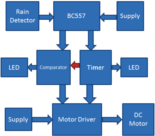
This Automatic Rain Sensing Wiper Control Circuit can be divided into four parts. First part includes 555 IC in Astable Mode, second part includes Comparator LM358, third part has Motor Driver circuitry using L293D and forth part is Rain Detector.
For Astable Multivibraror, we have used a 555 Timer IC for generating pulse in every 2-3 seconds (depends on capacitor value), means 555 Timer IC is configured in Astable mode. Output of Astable Multivibrator is directly connected to inverting pin of Comparator LM358 and Pin No 7 of Motor Driver L293D. Output of comparator is directly connected at pin 2 of motor driver IC. Comparator LM358 IC is used here for comparing 555 timer IC’s output voltage and reference voltage across comparator’s non inverting terminal, set by using Voltage Divider Circuit (R3 and R4). Two LEDs have been used, one at the output of 555 Astable circuit and other at the output of comparator LM358. A Water Detector or Rain Sensor is used for detecting the water or rain. Output of Astable Multivibrator and Comparator is applied to motor driver IC L293D, which will further drive the wiper motor. Whole circuit can be powered using 5v-12v battery depending upon the application.
Working Explanation:
Working of this Automatic Rain Sensing Car Wiper project is simple. As we already explained that this circuit has four parts namely Astable Multivibrator, Comparator, Motor Driver and Rain Detector. When water drops of rain falls over the Rain Sensor then it will trigger the PNP transistor BC557 and PNP transistor turns ON the power supply of whole circuit and circuit start working until there is water on the Rain Sensor. Now after the power supply has been turned ON, Astable Multivibrator starts oscillating in configured frequency.
Now when the output of 555 Timer IC goes HIGH then the comparator LM358 gives LOW output and when the output of 555 IC goes LOW then the Comparator’s output goes HIGH. And by using these two outputs DC motor turns clock wise and anticlockwise and wiper attached to it turns right to left and left to right, through Motor Driver IC L293D. That is how the wipers automatically sense rain and gets activated. They remain activated until there is water on Rain sensor, as soon as the water evaporates wipers get stopped. Two LEDs are also used here used for indication. You can see the whole working of this project in the Video below.
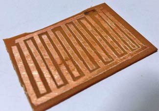
Building the Rain Sensor:
Rain Sensor is also called Rain Detector or Water Detector. Although they are easily available on any Electronic Shop or on any Online Electronic Store but you can also build them easily at your home. Here we are briefly explaining the steps:
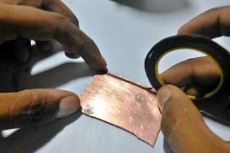
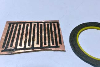
Step 1: Take Copper Clad Board of approx. 2 inch of length and same width and rub it by using the sand paper.
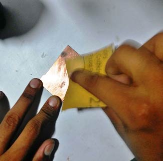
Step 2: Now take the Black tape or Cello tape and stick it to the Clad board as shown in the diagram.
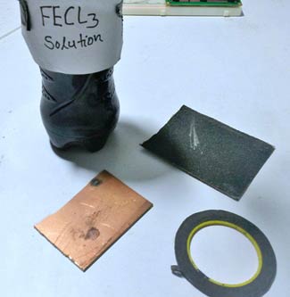
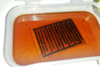
Step 3: We only need copper tracks under the black tape. So we need to remove all the other copper except under the black tape. For this, make Ferric chloride solution (FECL3), by adding 2-3 tea spoon of Ferric chloride in some water. This solution is called Itching Solution. Put the PCB in this solution for approx. half an hour.
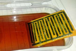
Step 4: Ferric chloride will react and remove the exposed copper and won’t react with the masked copper under the Black tape. Now take out the PCB from the solution without touching the solution and remove the Black tapes.
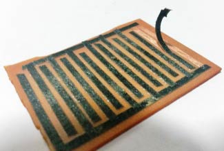
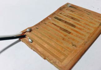
Step 5: Finally solder two wires on the two created coppers ‘tracks’ as shown in the figure and you have your Rain Sensor ready to use.
SOURCE : Circuit Digest
No comments:
Post a Comment