The Arduino Leonardo is a microcontroller board based on the ATmega32u4. It has 20 digital input/output pins (of which 7 can be used as PWM outputs and 12 as analog inputs), a 16 MHz crystal oscillator, a micro USB connection, a power jack, an ICSP header, and a reset button. It contains everything needed to support the microcontroller; simply connect it to a computer with a USB cable or power it with a AC-to-DC adapter or battery to get started.The Leonardo differs from all preceding boards in that the ATmega32u4 has built-in USB communication, eliminating the need for a secondary processor. This allows the Leonardo to appear to a connected computer as a mouse and keyboard, in addition to a virtual (CDC) serial / COM port.
Technical specifications
Arduino Leonardo
Microcontroller: ATmega32u4
Operating Voltage: 5V
Input Voltage (recommended): 7-12V
Input Voltage (limits): 6-20V
Digital I/O Pins: 20
PWM Channels: 7
Analog Input Channels: 12
DC Current per I/O Pin: 40 mA
DC Current for 3.3V Pin: 50 mA
Flash Memory: 32 KB (ATmega32u4) of which 4 KB used by bootloader
SRAM: 2.5 KB (ATmega32u4)
EEPROM: 1 KB (ATmega32u4)
Clock Speed: 16 MHz
How to Program Arduino Leonardo
Hardware and Software Required
Arduino Leonardo
Arduino IDE(1.0.6V)
Program to turn on the Led
void setup()
{
  pinMode(13, OUTPUT);// initialize digital pin 13 as an output.
}
void loop()// the loop function runs over and over again forever
{
digitalWrite(13, HIGH);   // turn the LED on (HIGH is the voltage level)
delay(1000);              // wait for a second
digitalWrite(13, LOW);    // turn the LED off by making the voltage LOW
delay(1000);              // wait for a second
}
In this post, we’ll build a great sounding audio amplifier with the LM386 Low Voltage Audio Power Amplifier IC. I built almost a dozen different audio amplifier circuits with the LM386 but most of them produced way too much noise, popping, and other interference. Finally I found one that sounds great. Granted, this is not a “minimal components” audio amplifier. There are lots of extra capacitors added to reduce the noise, and I’ve added a bass boost control as well to make it sound even better. Before we start building, it may be helpful to get a little background information…
LM386
The LM386 is quite a versatile chip. Only a couple resistors and capacitors are needed to make a simple audio amplifier. The chip has functions for gain control and bass boost, and it can also be turned into an oscillator capable of outputting sine waves or square waves.
The LM386 is a type of operational amplifier (Op-Amp). Operational amplifiers have a basic task. They take an input potential (voltage) and produce an output potential that is tens, hundreds, or thousands of times the magnitude of the input potential. In this circuit, the LM386 takes an audio input signal and increases its potential anywhere from 20 to 200 times. That amplification is what is known as the voltage gain.
Gain vs Volume
After you build this amplifier and play with the volume and gain controls, you will notice that both appear to raise or lower the intensity of sound coming out of the speaker. So what is the difference then? Gain is the amplification of the input potential. It is a characteristic of the amplifier. Volume lets you adjust the sound level within the range of amplification set by the gain. Gain sets the range of possible volume levels. For example, if our gain is set to 20, the range of volume is 0 to 20. If our gain is set to 200, the range of volume is 0 to 200.
The LM386 IC has 8 pins as shown in the diagram below:
The main pins to be aware of are pins 2 and 3, the audio signal inputs, and pin 5, the positive audio output signal. Gain control can be achieved by bridging pins 1 and 8 with a 10 μF capacitor. If pins 1 and 8 are not connected, the output gain will be 20. With only a 10 μF capacitor, the gain will be 200. The gain can be adjusted to any value between 20 and 200 by placing a potentiometer in series with the capacitor.
There are three varieties of the LM386, each with different output power ratings:
LM386N-1: 0.325 Watts
LM386N-3: 0.700 Watts
LM386N-4: 1.00 Watts
You can download the datasheet for the Texas Instruments LM386 here:
Now that we have a little background into the LM386, let’s build the amplifier. Just for comparison, I’ll show you how to make a minimal LM386 amplifier first, so you can compare it to the better sounding one we’ll build later on.
In the circuit above, the power supply, audio input signal, and audio output signal all flow through the same common path to ground. This causes interference in the output signal. To prevent this, we can connect the grounds for power, input, and output directly to the ground pin (pin 4) of the LM386 like this:
This should sound better than the first circuit, but you will probably still notice some noise, static and popping. To fix this, we need to add some decoupling capacitors. Decoupling capacitors isolate the amplifier circuit from signal interference caused by fluctuations in power and filter noise from the audio signal. Larger value capacitors will filter lower frequency noise while smaller value capacitors will filter out higher frequency noise.
The Great Sounding LM386 Audio Amplifier
Now that you’ve seen the bare minimum of what it takes to make an audio amplifier from the LM386, lets build a higher fidelity version, and add an adjustable gain control. Several things in this circuit make it sound better:
A 470 pF decoupling capacitor between the positive input signal and ground.
100 μF and 0.1 μF capacitors between the positive and negative power rails to decouple the power supply. The 100 μF capacitor will filter low frequency noise while the 0.1 μF capacitor will filter high frequency noise.
A 0.1 μF capacitor between pins 4 and 6, for additional decoupling of the power supply to the chip.
A 10K Ohm resistor and a 10 μF capacitor in series between pin 7 and ground to decouple the audio input signal.
The diagram below will show you how to connect everything:
One thing to keep in mind when you’re wiring LM386 circuits is that the cleanest sound will result from keeping all wire connections and components as close to the chip as possible. Keeping the wires as short as possible will also help.
The LM386 Audio Amplifier with Bass Boost Control
A cool feature of the LM386 is the option to add an adjustable bass boost to the amplifier. You’ll find that this is the best sounding circuit so far, since the low pass filter removes most of the noise not taken out by the decoupling capacitors. All you need for the bass boost circuit is a 0.033 μF capacitor and a 10K Ohm potentiometer in series between pins 1 and 5:
An easy way to input the audio in these circuits is with a 3.5 mm audio jack from an old set of headphones modified with breadboard pins. Check out this article, How to Hack a Headphone Jack to learn how to re-wire some common types of headphones.
You can watch the video version of this tutorial and listen to each amplifier here:
The Pro Micro is similar to the Pro Mini except with an ATmega32U4 on board.Like Pro mini,the Pro micro also comes in two different models i.e, 3.3v and 5v.The Pro micro 3.3v model has 8MHz crystal oscillator in its board whereas the Pro micro 5v model has 16MHz oscillator which differentiate them.
Arduino Pro Micro
Also notice the backside of board in which the model number is marked either 5v or 3.3v.If both of this signs are failed,check the jumper(J1) at the top left corner of the board which is closed for 5V and open for 3.3V.
Technical Specifications
Microcontroller - ATmega32U4
Operating Voltage - 3.3V or 5V (depending on model)
Input Voltage - 3.35 -12 V (3.3V model) or 5 - 12 V (5V model)
Digital I/O Pins - 20 (of which 7 provide PWM output)
There are no digital input pins 11,12,13 and 17 available on the controller board.
Digital pin 2 is SDA and Digital pin 3 is SCL which supports I2C communication.
Digital pin 16 is MOSI,15 is MISO and 14 is SCLK (or SCK) supports SPI communication.
The AREF input does not exist on the board.
The Analog pins(A0,A1,A2,A3) can also be configured as digital pins(D18,D19,D20,D21).
The Tilt sign(~) represents the PWM pin.
How to program Pro Micro?
Hardware and Software Required
Arduino Pro Micro(5v model used here)
Arduino IDE 1.0.6V
Program for Arduino Pro Micro
Like other Arduino,the Pro micro has no on board led.So we need to connect a led externally to the Pro micro board.Before uploading code to the board,select the board under tools menu as Arduino Micro.
void setup()
{
  pinMode(2, OUTPUT);// initialize digital pin 2 as an output.
}
void loop()// the loop function runs over and over again forever
{
digitalWrite(2, HIGH);   // turn the LED on (HIGH is the voltage level)
delay(1000);              // wait for a second
digitalWrite(2, LOW);    // turn the LED off by making the voltage LOW
delay(1000);              // wait for a second
}
The Arduino Pro Mini is a microcontroller board based on the ATmega328.It has 14 digital input/output pins (of which 6 can be used as PWM outputs), 6 analog inputs, an on-board resonator, a reset button, and holes for mounting pin headers. A six pin header can be connected to an FTDI cable or Spark fun breakout board to provide USB power and communication to the board.There are two version of the Pro Mini.One runs at 3.3V and 8 MHz, the other at 5V and 16 MHz.
Arduino Pro Mini
The Pro Mini is not physically compatible with Arduino shields (you could still hard-wire the Mini up to any Arduino shield).The Pro Mini uses the same ATmega328 and also has same 14 digital i/o pins,6 analog pins as in Uno.
Though it differs from Uno by some hardware changes such as,Size-Pro mini is just 1.3x0.70" and it is about 1/6th the size of the Arduino Uno,Operating voltage-Pro mini has only one regulator on board either 3.3V or 5V unlike Uno which has both 5V and 3.3V and the Clock Speed is 8MHz fro 3.3v model which is half the speed of Uno.
As said before,there are two versions of Pro mini(3.3v and 5v).So how to know the difference between this two will be worth mentioning.There is a voltage regulator on the Pro mini(red box shown in the image) which makes the difference.i.e If the label of that regulator is given as KB33 mean it is 3.3v model and KB50 means 5v model.Also you can measure the voltage between the Vcc and Gnd pin which determines the model.
Technical Specifications
Microcontroller - ATmega328
Operating Voltage - 3.3V or 5V (depending on model)
Input Voltage - 3.35 -12 V (3.3V model) or 5 - 12 V (5V model)
Digital I/O Pins - 14 (of which 6 provide PWM output)
Analog Input Pins - 6
DC Current per I/O Pin - 40 mA
Flash Memory - 32 kB (of which 0.5 kB used by bootloader)
RAW: For supplying a raw (regulated) voltage to the board
VCC: The regulated 3.3 or 5 volt supply
GND: Ground pins
RX: Used to receive TTL serial data
TX: Used to transmit TTL serial data
Digital I/O pins(2 and 3): These pins can also be configured to trigger an interrupt on a low value, a rising or falling edge, or a change in value
Digital I/O pins(3, 5, 6, 9, 10, and 11): They can also be configured to provide 8-bit PWM output
Digital I/O pins(10, 11, 12 and 13): They can also be configured as SPI pins-10 - (SS), 11 - (MOSI), 12 - (MISO) and 13 - (SCK)
Analog input pins: A0 to A7 in which A4 and A5 can also be used as IIC pins where A4 - (SDA) and A5 – (SCL).
Reset: The microcontroller can be reset by bringing this pin low
FTDI Platinum board
How to Program Arduino Pro Mini
Hardware and Software Required
Arduino Pro Mini 3.3v
Arduino IDE(1.0.6V)
For programming the Pro mini,either we need a FTDI TTL-232R-3V3 USB - TTL Level Serial Converter Cable or SparkFun FTDI Basic Breakout Board and USB Mini-B cable which connects the Pro mini to the computer.Here FTDI Platinum board is used as shown in the image.While connecting the FTDI board to Pro mini,the Gnd of Arduino should face Gnd of FTDI.
Program to turn on the Led
Like other Arduino,the Pro mini also has on board Led which we are going to blink it with one second delay.Before that,select the correct board and port in Arduino IDE.Here we are using Pro mini 3.3v/ATmega 328 board.
void setup()
{
   pinMode(13, OUTPUT);// initialize digital pin 13 as an output.
}
 void loop()// the loop function runs over and over again forever
{
 digitalWrite(13, HIGH);   // turn the LED on (HIGH is the voltage level)
 delay(1000);              // wait for a second
 digitalWrite(13, LOW);    // turn the LED off by making the voltage LOW
 delay(1000);              // wait for a second
}
The Arduino Mega 2560 is a microcontroller board based on the ATmega2560. It has 54 digital input/output pins (of which 14 can be used as PWM outputs), 16 analog inputs, 4 UARTs (hardware serial ports), a 16 MHz crystal oscillator, a USB connection, a power jack, an ICSP header, and a reset button. It contains everything needed to support the microcontroller; simply connect it to a computer with a USB cable or power it with a AC-to-DC adapter or battery to get started. The Mega is compatible with most shields designed for the Arduino Duemilanove or Diecimila.
Arduino Mega
The Arduino Mega is the addition to the Arduino family.This board is physically larger than all the other boards and offers significantly more digital and analog pins. The MEGA uses a different processor allowing greater program size and more.The Mega2560 differs from all preceding boards in that it does not use the FTDI USB-to-serial driver chip.Instead, it features the ATmega16U2 programmed as a USB-to-serial converter.The Mega has four hardware serial ports, which means maximum speed if you need a second or third (or fourth) port.The Arduino Mega works in the same way the Arduino Uno does but the difference is that it uses ATmega2560 microcontroller and has more number of digital pins,analog pins.
Technical Specifications
Microcontroller: ATmega1280 or 2560
Operating Voltage: 5V
Input Voltage(recommended): 7-12V
Input Voltage(limits): 6-20V
Digital I/O Pins: 54 (of which 14 provide PWM output)
Analog Input Pins: 16
DC Current per I/O Pin: 40 mA
DC Current for 3.3V Pin: 50 mA
Flash Memory: 128KB or 256KB
SRAM: 8 KB
EEPROM: 4 KB
Clock Speed: 16 MHz
How to program Arduino Mega?
The Arduino Mega can be programmed with Ardunio IDE like Arduino Uno. So the user can find it easy to program the Arduino Mega.
Hardware and Software Required
Arduino Mega2560
Arduino IDE(1.0.6 Version)
Program to turn on the Led
Before uploading the code to Mega,make sure that you have selected the correct board and port under the tools menu.The Arduino Mega has on board LED like Uno. The program given below turns the led on and off with one second time delay.You can find this program under the built-in examples of Arduino IDE.
void setup()
{
   pinMode(13, OUTPUT);// initialize digital pin 13 as an output.
}
 void loop()// the loop function runs over and over again forever
{
 digitalWrite(13, HIGH);   // turn the LED on (HIGH is the voltage level)
 delay(1000);              // wait for a second
 digitalWrite(13, LOW);    // turn the LED off by making the voltage LOW
 delay(1000);              // wait for a second
}
The Arduino Uno is the most common version of Arduino family.The Arduino Uno is a micro controller board based on the ATmega328.It has 14 digital input/output pins (of which 6 can be used as PWM outputs), 6 analog inputs, a 16 MHz ceramic resonator, a USB connection, a power jack, an ICSP header, and a reset button.The Arduino Uno is great choice for beginners.It contains everything needed to support the micro controller; simply connect it to a computer with a USB cable or power it with a AC-to-DC adapter or battery to get started.The Arduino Uno is a good choice for beginners since it is easy to start with.
Arduino UNO
A newbie to the Arduino environment may not know much about Arduino Uno board.Take a look into the following image which gives basic details about the Arduino Uno board.
USB: The USB port is used to power the board from the computer's USB port and also to transfer the program code from computer into the Arduino microcontroller.
External Power: It is used to power the board if the USB connector is not used.An AC adapter(9 volts,2.1mm barrel tip,center positive) could be used for providing external power.If there is no power at the power socket,then the Arduino will use power form the USB socket.But it is safe to have power at both the power socket and USB socket.
Digital Pins(I/O): The Arduino Uno has 14 digital pins(0 to 13) of which the 6 are PWM(~).This pins can be either inputs or outputs.But we need to mention it in the Arduino sketch(Arduino programming).The PWM(Pulse Width Modulated) pins acts as normal digital pins and also used to control some functions.Say for example,control the dimming of LED and control the direction of servo motor.Both digital inputs and digital outputs can read one of the two values either HIGH or LOW.
Analog Pins: The Analog pins(0 to 5) acts as inputs which is used to read the voltage in analog sensors such as temperature sensor,gas sensor,etc.Unlike digital pins which can only read one of the two values(HIGH or LOW),the analog inputs can measure 1024 different voltage levels.
ATmega Microcontroller: The Arduino uses ATmega328 microcontroller. It is a single chip microcontroller created by Atmel. This chip works well with Arduino IDE.If damaged,this controller can be easily replaced.The Atmega328 has 32 KB of flash memory for storing code (of which 0,5 KB is used for the bootloader).It has also 2 KB of SRAM and 1 KB of EEPROM.
3.3V Pin: A 3.3 volt supply generated by the on-board regulator. Maximum current draw is 50 mA.
5V Pin: The regulated power supply used to power the microcontroller and other components on the board. This can come either from an on-board regulator, or be supplied by USB or another regulated 5V supply.
Reset Button: It is used to reset the microcontroller. Pushing this button will temporarily connect the reset pin to ground and restart any code that is loaded on the Arduino.
Technical Specifications
Microcontroller- ATmega328
Operating Voltage- 5V
Input Voltage (recommended) - 7to12V
Input Voltage(limit) - 6to20V
Digital I/O Pins-14 (of which 6 provide PWM output)
Analog Input Pins-6
DC Current per I/O Pin-40 mA
DC Current for 3.3V Pin-50 mA
Flash Memory-32 KB (ATmega328) of which 0.5 KB used by boot loader
SRAM-2 KB (ATmega328)
EEPROM-1 KB (ATmega328)
Clock Speed-16 MHz
How to program Arduino Uno?
Hardware and Software Required
Arduino Uno
Arduino IDE
Arduino IDE
A sketch is the name that Arduino uses for a program.It is the unit of code that is uploaded to and run on an Arduino board to execute the function like blinking a Led. To write a sketch,we need to install the Arduino Software known as Integrated Development Environment(IDE).
Program to turn on the Led
The Arduino Uno has on board LED.The program given below turns the led on and off with one second time delay.You can find this program under the built-in examples of Arduino IDE.Before uploading the sketch to the Arduino board,make sure that you have selected the correct board and serial port under the tools menu.
Output for the program
void setup()
{
   pinMode(13, OUTPUT);// initialize digital pin 13 as an output.
}
 void loop()// the loop function runs over and over again forever
{
 digitalWrite(13, HIGH);   // turn the LED on (HIGH is the voltage level)
 delay(1000);              // wait for a second
 digitalWrite(13, LOW);    // turn the LED off by making the voltage LOW
 delay(1000);              // wait for a second
}
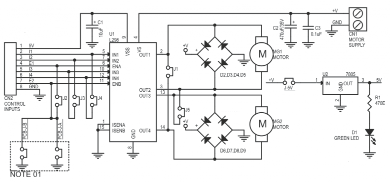
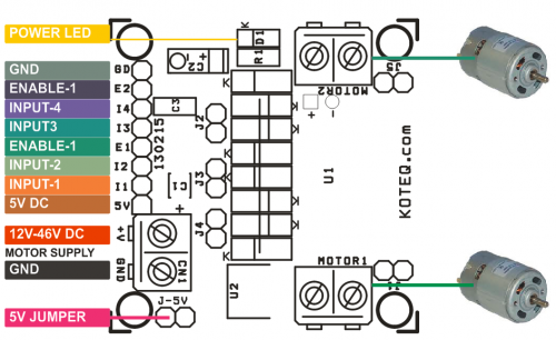
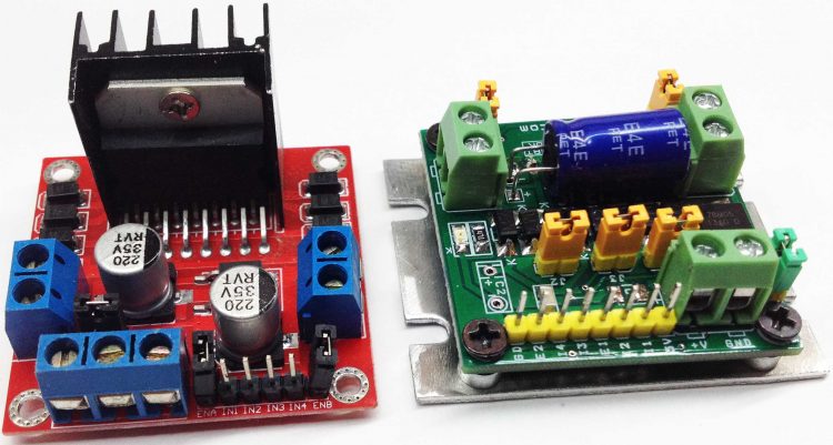
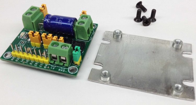
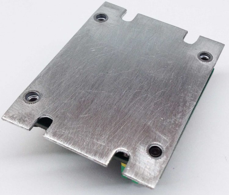
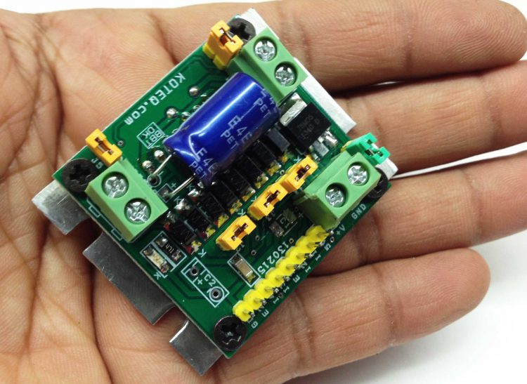
Dual Motor L298 H-Bridge Control project can control two DC motors connected to it. The circuit is designed around popular dual H-Bridge L298 from ST. This board can be configured to drive a single motor with high current rating also. This can be achieved with the help of jumpers on the board. An onboard 5V regulator can take a maximum of 18V of DC input. Should you wish to drive this board with higher voltage then 18V, you will need to connect a external 5V regulated source to the logic circuit. For this you will need to remove J-5V. This board can fit in any small toy or robot due to small size and very low profile. L298 IC is mounted under the PCB in horizontal position to make board small and low profile to fit any small robot. On board 5V regulator can be used to power up external Micro-Controller board as well as internal logic supply.
Features
Motor supply: 7 to 46 VDC
Open J-5V Jumper if Input Motor Supply is above 18V ( Required External 5V for Logic)
Control Logic Input: Standard TTL logic level
Output DC drive to motor: up to 2 A each (Peak)
On Board 5V Regulator (Close J-5V to Use On Board 5V Regulator)
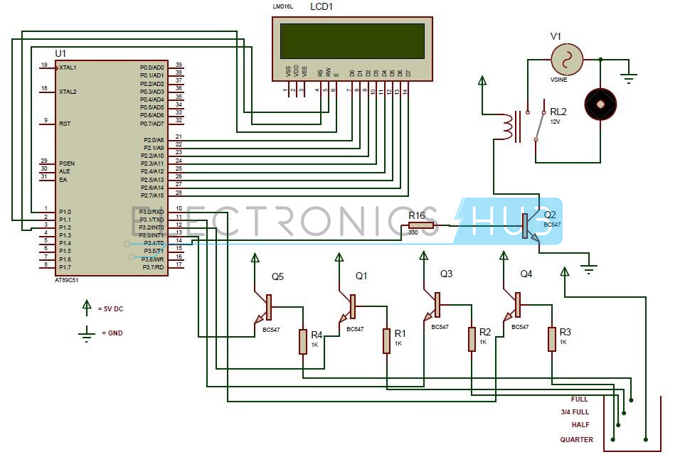
This article explains you how to detect and control the water level in an overhead tank or any other container. This system monitors the water level of the tank and automatically switches ON the motor when ever tank is empty. The motor is switched OFF when the overhead tank or container is FULL. Here the water level of the tank is indicated on LCD (Liquid crystal Display). Using this system, we can avoid the overflow of the water. But, here we are designing the circuit which is used to detect and control the water level automatically in overhead tank using 8051 microcontroller.
In this system water sensing can be done by using a set of 4 wires which are placed at different levels in tank. DC supply probe is placed at the base of the tank.
Water Level Controller using 8051 Circuit Principle:
This system mainly works on a principle that “water conducts electricity”. The four wires which are dipped into the tank will indicate the different water levels. Based on the outputs of these wires, microcontroller displays water level on LCD as well as controls the motor.
Water Level Controller using 8051 Circuit Diagram:
Circuit Diagram of Water Level Controller using 8051 Microcontroller
Circuit Components:
At89c51 controller
At89c51 programming board.
16*2 LCD
5V Relay
Bc547 (NPN) transistors – 5
Resistors (1K) – 4
Resistor – 330 ohm
AC Motor
Pot – 10k
Programming cable
Connecting wires
Water Level Controller using 8051 Circuit Design:
The main heart of this project is AT89C51 microcontroller. The water level probes are connected to the P3.0, P3.1, P3.2, and P3.3 through the transistors. Port P2 connected to the data pins of LCD and control pins RS, RW and EN of LCD are connected to the P1.0, P1.1, and P1.2 respectively.
Initially when tank is empty, LCD will display the message EMPTY and motor runs automatically. When water level reaches to quarter level, now LCD displays QUARTER and still motor runs. For further levels, LCD displays the messages HALF and ¾ FULL.
When tank is full, LCD displays FULL and motor automatically stops. Again motor runs when tank is empty.
Algorithm for Water Level Controller Circuit:
First configure the controller pins P3.0, P3.1, P3.2 and P3.3 as inputs and P3.4 as output.
Now initialize the LCD.
Continuously check the water level input pins P3.0, P3.1, P3.2, and P3.3
If all the pins are low then display tank is empty on LCD and make P3.4 pin high to run the motor automatically.
High pulse on the pin P3.0 indicates quarter level, display the same thing on LCD.
If P3.1 is high then water level is half.
High pulse on P3.2 indicates 3/4th full of the tank.
If P3.3 is high then tank is full, now make P3.4 pin is low to turn off the motor automatically.
Water Level Controller using 8051 Circuit Simulation Video:


 Circuit Diagram of Water Level Controller using 8051 Microcontroller