Tuesday, 16 May 2017

Ransomware Facts by Microsoft Security Support


Ransomware

Ransomware stops you from using your PC. It holds your PC or files for "ransom". This page describes what ransomware is and what it does, and provides advice on how to prevent and recover from ransomware infections.
You can also read our blog about ransomware: The 5Ws and 1H of ransomware. 
On this page:

What does ransomware do?

There are different types of ransomware. However, all of them will prevent you from using your PC normally, and they will all ask you to do something before you can use your PC.
They can target any PC users, whether it’s a home computer, endpoints in an enterprise network, or servers used by a government agency or healthcare provider.
Ransomware can:
  • Prevent you from accessing Windows.
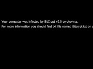
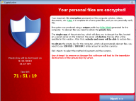
  • Encrypt files so you can't use them.
  • Stop certain apps from running (like your web browser).
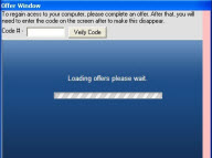
Ransomware will demand that you pay money (a “ransom”) to get access to your PC or files. We have also seen them make you complete surveys.
There is no guarantee that paying the fine or doing what the ransomware tells you will give access to your PC or files again.

Details for home users

There are two types of ransomware – lockscreen ransomware and encryption ransomware.
Lockscreen ransomware shows a full-screen message that prevents you from accessing your PC or files. It says you have to pay money (a “ransom”) to get access to your PC again.
Encryption ransomware changes your files so you can’t open them. It does this by encrypting the files – see the Details for enterprises section if you’re interested in the technologies and techniques we’ve seen.
Older versions of ransom usually claim you have done something illegal with your PC, and that you are being fined by a police force or government agency.
These claims are false. It is a scare tactic designed to make you pay the money without telling anyone who might be able to restore your PC.
Newer versions encrypt the files on your PC so you can’t access them, and then simply demand money to restore your files.
Ransomware can get on your PC from nearly any source that any other malware (including viruses) can come from. This includes:
  • Visiting unsafe, suspicious, or fake websites.
  • Opening emails and email attachments from people you don’t know, or that you weren’t expecting.
  • Clicking on malicious or bad links in emails, Facebook, Twitter, and other social media posts, instant messenger chats, like Skype.
It can be very difficult to restore your PC after a ransomware attack – especially if it’s infected by encryption ransomware.
That’s why the best solution to ransomware is to be safe on the Internet and with emails and online chat:
  • Don’t click on a link on a webpage, in an email, or in a chat message unless you absolutely trust the page or sender.
  • If you’re ever unsure – don’t click it!
  • Often fake emails and webpages have bad spelling, or just look unusual. Look out for strange spellings of company names (like “PayePal” instead of “PayPal”) or unusual spaces, symbols, or punctuation (like “iTunesCustomer Service” instead of “iTunes Customer Service”).
Check our frequently asked questions for more information about ransomware, including troubleshooting tips in case you’re infected, and how you can backup your files to help protect yourself from ransomware.

Details for enterprises and IT professionals

The number of enterprise victims being targeted by ransomware is increasing. Usually, the attackers specifically research and target a victim (similar to whale-phishing or spear-phishing – and these in fact may be techniques used to gain access to the network).
The sensitive files are encrypted, and large amounts of money are demanded to restore the files. Generally, the attacker has a list of file extensions or folder locations that the ransomware will target for encryption.
Due to the encryption of the files, it can be practically impossible to reverse-engineer the encryption or “crack” the files without the original encryption key – which only the attackers will have access to.
The best advice for prevention is to ensure company-confidential, sensitive, or important files are securely backed up in a remote, un-connected backup or storage facility.
OneDrive for Business can assist in backing up everyday files.
In some cases, third-party tools released by some security firms are able to decrypt files for some specifically ransomware families. See our blog FireEye and Fox-IT tool can help recover Crilock-encrypted files for an example. Tim Rains, Microsoft Director of Security, released the blog Ransomware: Understanding the risk in April 2016 that summarizes the state of ransomware and provides statistics, details, and preventative suggestions to enterprises and IT professionals: Our Threat intelligence report: Ransomware also includes suggestions on prevention and recovery, statistics, and details.

Prevalent ransomware

Globally, ransomware continues to be a problem. In particular, we’ve seen increases in Italy and the eastern seaboard of the US.
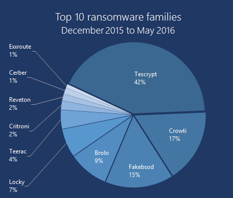
The past six months (between December 2015 and May 2016) have seen the rise of Tescrypt globally. Crowti remains near the top of the pack, as does Brolo and FakeBsod.
Reveton has also dropped down the ladder, now at 1% of the top 10 share, down from 7% for the preceding 6 months.
Pie chart showing US with 50% of all detections, followed by Italy, Canada, and other countries across the world
Figure 1. Top 10 Ransomware (December 2015 to May 2016)      
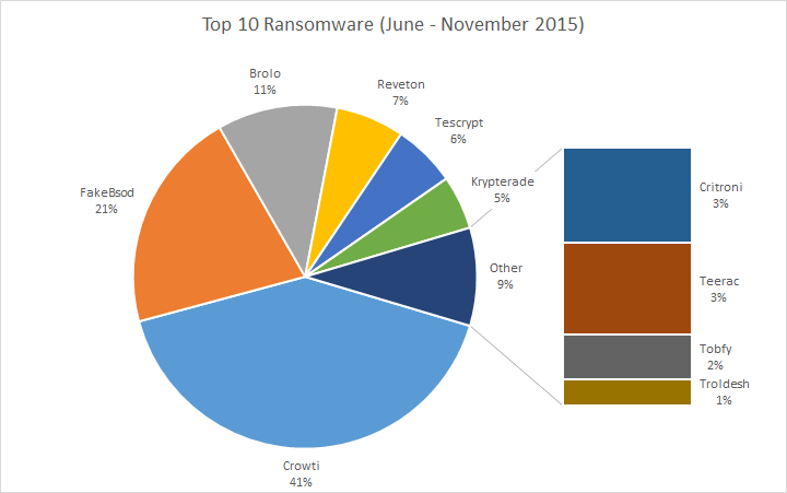
Top 10 ransomware for June 2015 to November 2015
Figure 2. Top 10 Ransomware (June to November 2015)      
For the top 10 countries with the most detections, the United States takes a full half of all detections. Italy is second, followed closely by Canada, Turkey, and the United Kingdom. After that the distribution is spread across the globe.
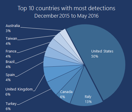
Pie chart showing top ransomware families, including Tescrypt (42%), Crowti (17%) and Fakebsod (15%)
Figure 3: Top 10 countries (December 2015 to May 2016)
The greatest detections in the US were for FakeBsod, followed by Tescrypt and Brolo. Tescrypt was also prevalent in Italy.
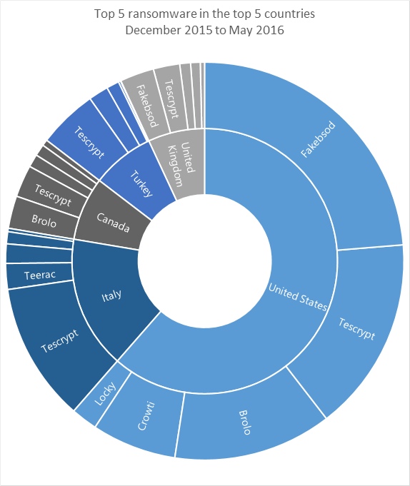
Sunburst graphic showing the top countries and ransomware, including Fakebsod, Tescrypt, Brolo, and Crowti for the US, and Tescrypt for Italy
Figure 4: Top detections in top countries (December 2015 to May 2016)
FakeBsod uses a malicious piece of JavaScript code to lock your web browser and show a fake warning message when you visit a compromised or malicious webpage. The warning message tells you to “contact Microsoft technicians” about an “Error 333 Registry Failure of operating system – Host: Blue screen Error 0x0000000CE”. If you call the phone number in the message you will be asked to pay money to “fix” the issue.
An example of the fake warning message is shown in Figure 5:

Fakebsod lock screen image that locks like a Windows error blue screen
Figure 5: Message used by FakeBsod to lock your web browser
You can regain control of your web browser without paying anything by closing the warning message using the Task Manager.
When you reopen your browser, make sure you don't click Restore previous session.
Read more about this threat in the Ransom:JS/FakeBsod.A description.

Wednesday, 3 May 2017

Home Automation and Weather Monitor Using IOT


Home Automation and Weather Monitor Using IOT or 
Controlling Appliances and Weather Monitor Using IOT
In this video I will show you how to make an IoT device which is capable of controlling the appliances and realtime weather monitoring . This device is build using ESP8266 node mcu.
Esp8266 node mcu is a device with built in wifi module and microcontroller which can interface with arduino ide .

Dashboard : for this project I used cayenne IOT platform because it is easy to configure and good user interface with drag and drop option.
For complete construction : https://www.instructables.com/id/Cont... 
----------------------------------------------------------------------------------------------------------
Libraries and Fritzing files : https://goo.gl/POHhtH 
Code : https://goo.gl/Ep0bC4

##############BUY COMPONENTS HERE###############

Relay Board : https://goo.gl/ikC1pv 
Node Mcu esp8266 : https://goo.gl/8ebGlD 
DC jack : https://goo.gl/hePJcp 
Perfboard : https://goo.gl/HySMY4 
IC7805 : https://goo.gl/RARAvQ 
Header Pins : https://goo.gl/5K6crS 
DHT 11 Module : https://goo.gl/XcK84x

Buy all components Here : https://goo.gl/JYah69

Paypal: https://goo.gl/AiuYzE 
Patreon : https://www.patreon.com/techmaker/
By funding me , I will get some revenue to purchase components.

Tuesday, 2 May 2017

Dual Laser Security System Using An Old Feature Phone

A security system having a single laser beam may not be very effective as any moving object or animal can interrupt it, causing a false alarm. Presented here is a security system having two laser beams with calling alert feature, using a basic mobile phone (old model), also known as feature phone.
The security system can be used in a restricted area like a farm or as a home security system. When an intruder cuts or interrupts both laser beams at the same time, an alarm sound is generated and an alert call is made to your current mobile phone.


Circuit and working

Circuit diagram of the laser security system using a basic feature phone is shown in Fig. 1. It is built around two light-dependent resistors (LDR1 and LDR2), five transistors (T1 through T5), one diode (D1), one NE555 timer (IC1) and a few other components.
T3 and T4 are configured as NAND gate. NE555 is configured in monostable mode. T5 is used to drive relay RL1 and piezo buzzer PZ1. Relay contacts are connected to the old basic feature phone through connector CON2.

                      Fig. 1: Circuit diagram of the laser security system

When two laser beams falling on LDR1 and LDR2 are interrupted at the same time, T1 and T2 conduct, making T3 and T4 also to conduct. Output signal at collector of T3 is given to trigger pin 2 of IC1 through toggle switch S1. As a result, LED1 goes off and T5 conducts.
PZ1 sounds for a pre-fixed time based on the values of resistor R8 and capacitor C1. At the same time, RL1 gets energised and activates the speed dial function of the feature phone through CON2. The speed dial function is assigned with a specific contact number like your current mobile phone number. You thus get an alert through an incoming call on your phone.

Construction and testing

An actual-size, single-side PCB for the laser security system is shown in Fig. 2 and its component layout in Fig. 3. After assembling the circuit on a PCB, enclose it in a suitable box.

       
Fig. 2: Actual-size PCB layout of the laser security system


                                 Fig. 3: Component layout of the PCB

The circuit works off a 6V battery or power supply. Refer Fig. 4 for the proposed installation of laser beams and mirrors for the security system.


Fig. 4: Proposed installation of laser beams along with mirrors for the security system

Switch S1 to off position during installation of the laser beams and LDRs.
The project requires two mobile phones—one old basic feature phone, which will be connected to the circuit, and the other could be the mobile phone you may already be using.
Normally, button 1 on a feature phone is assigned for speed dial function. Open the cover of the dial pad of this feature phone. Solder two wires on the PCB at 1 (Fig. 5). Extend these wires to CON2 in the circuit.


                   Fig. 5: Mobile connection

You can install the two laser beams at a slight distance from each other, depending on what you want to guard against. For example, to guard your farm against cattle, keep the two laser beams about 90cm apart, so that the animal interrupts both the laser beams when it crosses the gate of your farm. As soon as animal enters your farm, this system will alert you, and you can take instant action. With the two laser beams kept 90cm apart, a human being crossing the gate of your farm will not produce an alarm or send an alert to your mobile phone, thus preventing a false alarm.

Monday, 1 May 2017

Microcontroller Projects and Project Ideas

The role of a microcontroller in the life of a design engineer is immense. These provide integrated solutions for engineers incorporating multiple peripherals along with the much-needed processor in a small sized module. You might have one lying in your electronics spare parts box. Let’s put them to good use with some microcontroller projects. This list of top 20 microcontroller project ideas might come in handy if you plan on something.

Contents


Microcontroller Projects: Wireless systems


Interface GSM Module

GSM is widely used mobile communication architecture used in most of the countries. This project demonstrates the interfacing of micro controller AT89C51 with Hyper Terminal and GSM module. It aims to familiarize with the syntax of AT Commands and their Information Response and Result Codes. The ASCII values of characters in the Information Response, Result Codes and their syntax can be monitored by an LED array.
This project is available at: Interface GSM Module

GSM based home security

In this project, we are developing a passive infrared (PIR) sensor and GSM based home security system. PIR sensors are used to detect living being movement. This project is developed using 8051 microcontrollers. It can be used to detect any intrusion in houses and offices with options of sending alerts on cell phones. Let us know how to develop this system, step by step.
This project is available at: GSM based security

ATmega16A Based GPS Receiver

A global positioning system (GPS) receiver uses information from the satellites to get precise geographical location. It not only gives information about location but also information like time, date, height and speed. The project here demonstrates how to get location (latitude and longitude), time, date, speed and course-angle information using a GPS receiver. It uses 8-bit AVR microcontroller (MCU) ATmega16A to get data from the GPS receiver.
This project is available at: ATmega16A Based GPS Receiver

Ultrasonic Radar

Radar systems have several defence as well as civil applications. A transmitter, transmits a beam towards the target. This is reflected by the target as an echo signal. The reflected signal is received by a receiver. This receiver processes the received signal and provides information about the presence of a target, distance, position (moving or stationary) or speed. This is displayed on a display unit.
This project is available at: Ultrasonic Radar

Microcontroller Projects: Locks


Digital Code Lock

Security is a major concern in our day to day life, and digital locks have become an important part of these security systems. Today there are digital locks operable from smart phones. This project explains a simple electronic code lock using 8051 microcontrollers. It can only be unlocked by a predefined code. The system alerts by sounding the buzzer on entering incorrect password.
This project is available at: Digital code lock

Electronic Card Lock

This next project presents a circuit for an electronic lock. A rectangular card is inserted like a CD, inside the disk drive. An appliance is switched on depending on the positions of the holes in the card. The electronic lock is connected to an access control system to prevents false operation of the system. It ensures the switching “ON” of only the selected appliance.
This project is available at: Electronic Card Lock

Morse code encoder

Morse code is a method of transmitting textual information as a series of on-off tones, lights or clicks. The International Morse Code encodes alphabets, numerals and a small set of punctuation and procedural signals as standardised sequences of short and long signals called ‘dots’ and ‘dashes,’ respectively. The Morse code encoder presented here converts texts, numbers and special characters into Morse code as audible output on a piezo buzzer.
This project is available at: Morse code encoder

Microcontroller Projects: Robotics


Cell Phone Controlled Robot

In this project, we are going to build a cell phone controlled robot using 8051 microcontrollers. Cell phone controlled robot runs over mobile DTMF technology. DTMF stands for Dual Tone Multiple Frequency. There are some frequencies that we use to create DTMF tones. In simple words by adding or mixing two or more frequencies we generate DTMF tone.
This project is available at: Controlling Robot via cell phone

Edge Avoider Robot

An edge avoider robot is quite similar a line follower robot. In these types of robots, we generally use behaviour of light at black and white surface. A white surface reflects almost all the light, whereas black surface absorbs most of it. This behaviour of light is used in a line follower robot as well as edge avoider robot. This 8051-microcontroller based robot detects an edge and avoids it by turning or stopping. Let us see how can we design an edge avoider robot easily.
This project is available at: Edge avoiding robot

Microcontroller Projects: Smart Living


Restaurant menu ordering system

In these modern days, the number of restaurants are increasing. They also require very fast processing for serving food to the customers. With the increasing number of customers, it would require more manpower, since the current situation has become hectic for the restaurants. Also, changes in the hardcopy of the menu can’t happen.
This project is available at: Restaurant menu ordering system

Fridge Temperature and Humidity Indicator

We can measure temperature and humidity inside the fridge using a normal temperature-humidity indicator but relative humidity (RH) could be inaccurate in that case. The moment the fridge door is opened, RH will shoot up due to ingress or egress of moisture in the surroundings. The small sniffer device, described in this project, picks up temperature and humidity from inside the fridge and transmits on an RF link to a nearby receiver unit. The receiver unit checks the received code, identifies the right sniffer device and displays live temperature and humidity.
This project is available at: Fridge Temperature and Humidity Indicator

Home Automation System

We are surrounded by smart devices capable of making decisions with minimal human intervention. Our home can also be made smart by implementing real-time home automation systems. It monitors parameters like power consumption and human presence. Home automation may include centralised control of electrical devices including lightings, appliances and security. Presented here is a touch-control based home automation system that can control up to six electrical devices. It also has a separate keyboard interface module for troubleshooting and system settings.
This project is available at: Home Automation System

LPG Leakage Detector

Presented here is a low-cost circuit for an LPG detector that you can build easily. The main objective of the circuit is to detect LPG leakage anywhere. It is very easy to find gas leakages with this circuit, which uses low-cost components and an interactive way to adjust different sensitivity levels, based on customer needs, with the help of pot meter.
This project is available at: LPG Leakage Detector

Solar Tracker System

Solar energy is coming up as a major source of energy. The need of the hour is renewable energy resources with cheap running costs. With the current systems for solar energy harvesting, we have high production only at fixed times mostly noon. This project proposes a dual axis solar tracker system that increases the productivity by a significant margin.
This project is available at: Solar Tracker

Microcontroller Projects: Lighting


Display Custom Animations

Animating custom made characters on a 16×2 LCD screen can be very exciting. (Also, see LCD custom characters.) This topic explains the principle and operation of a displaying animation on LCD using Microcontroller AT89C51. There’s a useful side effect to the way the LCD controller uses CG RAM. Normally, we define a pattern in CG RAM, and then print the character. But it is also possible to change the CG RAM for characters that are already on the screen, and their appearance will change
This project is available at: Display Custom Animations

Auto Intensity Control of Street Lights

Street lights are controlled manually in olden days. These days’ automation of street lights has emerged. But one can observe that there is no need of high intensity in peak hours i.e. when there is no traffic and even in early mornings. By reducing the intensity in these times, energy can be saved to some extent. The project proposes circuits that control street light intensity by calculating the peak hours.
This project is available at: Auto Intensity Control of Street Lights

Microcontroller Projects: Miscellaneous


Odometer

This next project describes how to build a digital speedometer-cum-odometer for your motorbike. The circuit uses a microcontroller, an LCD display and some commonly available components. It is a better alternative to the mechanical speedometer and even a beginner with minimal skill level can assemble it.
This project is available at: Odometer

Microcontroller-Based Tachometer

A tachometer is nothing but a simple electronic digital transducer. Normally, it is used for measuring the speed of a rotating shaft. The number of revolutions per minute (rpm) is valuable information for understanding any rotational system. This easy-to-make photoelectric tachometer measures the rpm of most shop-floor tools and many household machines without any mechanical or electrical interface.
This project is available at: Microcontroller-Based Tachometer

Automatic Railway Gate Controller

At present, a gate keeper manually opens or closes railway gates. The nearby station informs the gatekeeper of the arrival of the train. However, some railway crossings are totally unmanned. The possibility of railway accidents occurring at these unmanned level crossings is high. One way to avoid accidents would be to automate this process. This project deals with an interesting manner of automating the railway gate control. The gate automatically opens or closes by detecting the arrival or departure of the train.
This project is available at: Automatic Railway Gate Controller

Interfacing Humidity Sensor

Various sensors are used to measure physical quantities in analogue form like pressure and temperature. This article demonstrates the principle and operation of interfacing the humidity sensor with 8051 microcontroller (AT89C51). A humidity sensor is widely used in applications like weather forecast, air conditioner, Hygrometers etc.
This project is available at: Interfacing humidity sensor

Ultrasonic Distance Meter Using Raspberry Pi 2

Ultrasonic ranging module HC-SR04 provides 2cm to 400cm non-contact distance measurement range. Its accuracy can reach ±3mm with a cycle period of 50ms, which is the minimum time delay recommended before measurements are taken. The module includes ultrasonic transmitter, receiver and control circuit.
Raspberry Pi 2 is a second-generation Raspberry Pi board, which was released in February 2015. It is a Linux based computer with a powerful Broadcom BCM2836 ARMv7 900MHz quad-core processor and 1GB SDRAM. It runs on 5V DC at 200mA and has 40 GPIO pins, along with HDMI, micro-SD card slot, Ethernet, USB 2.0 and 3.5 audio (out) ports.

Circuit and Working

Components required for this project are Raspberry Pi (or Raspi) 2, HC-SR04 module, 330-ohm and 470-ohm resistors, and some jumper wires.
Working of HC-SR04 ultrasonic sensor is fairly simple. Circuit diagram of Raspi with HC-SR04 is shown in Fig. 3. The HC-SR04 module and its working are shown in Figs 1 and 2, respectively.
HC-SR04 ultrasonic sensor module
Fig. 1: HC-SR04 ultrasonic sensor module
                    Fig. 2: Working of HC-SR04
                  
                                     Fig. 3: Connection of HC-SR04 module with Raspi
When the processor gives a high signal to trig pin of the sensor, the sensor emits out eight-cycle sonic bursts at 40kHz. After sending the sonic burst, the sensor sets echo to high till the sonic burst returns to the sensor—after reflection from the object. Hence, length of this pulse is proportional to how far the object is.
Now, distance covered by the pulse is twice the distance that has to be measured, and speed of sound is roughly 340 metres per second. Calculations can be carried out using the following relationship:
Speed=Distance/Time, or
340=(2×Distance)/Time, or
Distance=170×Time
Hence, distance between the object and the sensor in metres can be determined. To calculate in centimetres, multiply it by 100.
Connect HC-SR04 to Raspi as indicated below (also refer Fig. 3)
HC-SR04Raspi pins
VCC (+5V)Pin 2 (VCC)
TRIGPin 16 (GPIO 23)
ECHOPin 18 (GPIO 24)
GNDPin 34 (GND)
Resistors R1 and R2 are used to balance out the output as the sensor’s high signal is at +5V, whereas Raspi works on +3.3V level.
Hence, the voltage divider helps in reducing the output voltage level.

Software

There are many operating systems designed for Raspi 2, but the most widely used are Raspian (Linux based) and Microsoft Windows 10 IoT Core. If you are a newbie to Raspi 2, check out the link: www.raspberrypi.org/help for information on Raspi. In this project, the compiler used is Python and operating system for Raspi is Raspbian. The objective is to measure the distance between the sensor and an object that is kept at an unknown distance from the sensor.
There are some packages that are required for interfacing of HC-SR04. In order to download these packages, start Terminal on Raspi and execute the commands given below. Make sure that your Raspi is hooked to the Internet, otherwise the commands will not work.
After logging on, update Raspi using the commands given below. This ensures that you have the latest software and drivers installed.
 pi@raspberrrypi ~$ sudo apt-get update
pi@raspberrrypi ~$ sudo apt-get upgrade 
Following commands get you some common Python tools:
pi@raspberrrypi ~$ sudo apt-get install python-dev
// This should install python development tools
pi@raspberrrypi~$sudo wget http://pypi.python.org/packages/source/R/RPi.GPIO/RPi.GPIO-0.6.1.tar.gz
// Downloads the GPIO package
pi@raspberrrypi ~$ sudo tar zxf Rpi.
GPIO-0.6.1.tar.gz
// Extracts the package
pi@raspberrrypi ~$ cd Rpi.GPIO-0.6.1
//This should change the directory to Rpi GPIO folder
pi@raspberrrypi ~$ sudo python setup.py install
// This will install GPIO package on Raspi 
To make sure things are in order, reboot your Raspi by typing the following command:
pi@raspberrrypi ~$ sudo reboot 
Now all packages required for interfacing of HC-SR04 with Raspi have been installed.

Python code

Start Raspi and create UltraTest folder. For this tutorial, libraries used are RPi.GPIO and time. Create a new file (Ultra_Test.py) in nano editor using the commands given below:
pi@raspberrrypi ~ $ cd ~/Desktop/UltraTest
// Change Directory to UltraTest
pi@raspberrrypi ~/Desktop/UltraTest
$ sudo nano Ultra_Test.py
// Write python script as Ultra_Test.py

Press ctrl+o to save your Python script followed by pressing ctrl+x to exit.

Construction and Testing

After saving the code and connecting HC-SR04 to Raspi, boot Raspi. From the terminal, type the following commands to execute your program. Destination folder is UltraTest and file name is Ultra_Test.py as shown in Fig. 4.
Output screen of Raspi terminal window
Fig. 4: Output screen of Raspi terminal window
pi@raspberrrypi ~/Desktop/UltraTest
$ sudo python Ultra_Test.py
This Python script should measure the distance between the desired object and the sensor in centimetres. Refer Fig. 4 for the output screenshot of Raspi.

Download source code

For more info : Click Here